USDM 91-92 Mechanical Cluster to 93+ JDM Conversion
By hmong337
Are you sick of replacing those unreliable mechanical speed sensors? Or, maybe you got a JDM cluster with your 93+ JDM engine/transmission/clip and don’t want to deal with finding a mechanical speed sensor? I’ve got the perfect solution for you! Plus, this write-up is to finally lay this topic to rest.
Astonishingly, this conversion cost me as much as buying a used mechanical speed sensor. So not only is it a great alternative, but also a cost effective solution. 93+ JDM electronic clusters sell for barely anything; as do the electronic speed sensors. So if when your mechanical unit dies, you’re better off converting to electronic. It’s a lot more reliable and smoother too!
Be done with this:
-Cracked speedometer sensor gear shaft
http://i94.photobucket.com/albums/l107/hmong337/MR2%20Electric%20Cluster%20Conversion/IMG327.jpg
-Worn out sub-assembly pin
http://i94.photobucket.com/albums/l107/hmong337/MR2%20Electric%20Cluster%20Conversion/IMG329.jpg
The items you will need are:
-93+ JDM electronic cluster
-Electronic cluster plugs (Grab an extra one if you can. You may need to salvage pins from it later)
-Electronic speed sensor w/ its pigtail (female plug)
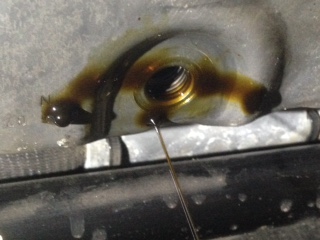
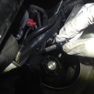
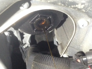
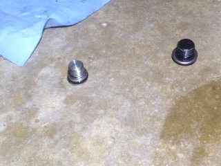
Step 1: Install your electronic speed sensor into the transmission. Here is an install link: (big thanks to: The homepage of Stephen Mason (http://www.stephenmason.com). His work can be found here: MR2 Speedometer sub-assembly replacement How-To (http://stephenmason.com/cars/mr2speedo.html))
***The link is for installing a mechanical unit. But it’s no different for the electronic unit.
Step 2: Cut off the triangle plug that went into your old mechanical speed sensor and splice on your new 93+ electronic plug/pigtail. There should be three wires.
91-92: 93+ JDM
white/black (ground) ——> brown (ground)
black/yellow (power) ——> black/yellow (power)
violet (speed signal) ——-> yellow/red (speed signal)
Here is a picture of the 91-92 triangle plug.
http://i94.photobucket.com/albums/l107/hmong337/MR2%20Electric%20Cluster%20Conversion/IMG276.jpg
Here is a picture of the 93+ JDM electronic plug.
http://i94.photobucket.com/albums/l107/hmong337/MR2%20Electric%20Cluster%20Conversion/IMG334.jpg
Step 3: Remove your old mechanical cluster. Follow this link: (big thanks to MR2OC member: fosley)
http://www.mr2.com/forums/mk2-interior-stereo-modifications/Toyota-MR2-29633-how-replace-gauge-cluster-bulbs.html
Now, let’s compare clusters
http://i94.photobucket.com/albums/l107/hmong337/MR2%20Electric%20Cluster%20Conversion/IMG280.jpg
http://i94.photobucket.com/albums/l107/hmong337/MR2%20Electric%20Cluster%20Conversion/IMG289.jpg
***NOTE: If your JDM cluster didn’t come with plugs, you can find them from Toyota Camry’s of 93-96 and 97-2000. I think the V6 Camry’s of 97-2000 have all three plugs but I’m not 100% sure. I was lucky my JDM cluster came with plugs. But it’s not a big deal. You can find all three at junkyards pretty easily. While you’re there, make sure you grab an extra plug to salvage pins from. Anyways, here are the part numbers:
90980-11114 blue plug “B”
90980-11115 brown plug “A”
90980-11116 gray plug “C”
Step 4: For the JDM unit, you’re going to have to swap the mounting brackets over from your USDM unit. They are different as the JDM uses RHD brackets and the USDM uses LHD brackets. See here:
http://i94.photobucket.com/albums/l107/hmong337/MR2%20Electric%20Cluster%20Conversion/IMG284.jpg
Now is the perfect time to do an LED light bulb conversion. I got four of these for like $4 shipped on Ebay. I highly recommend these.
http://i94.photobucket.com/albums/l107/hmong337/MR2%20Electric%20Cluster%20Conversion/IMG288.jpg
The stock turbo gauge is a waste of space. So, I went ahead and swapped my NA volt-meter to the 93+ JDM cluster. These are the pins/screws you’re going to have to jump in order to get your volt-meter to work. (Big thanks to 5sfeTurbo.Com: MR2 | Celica | Camry | Turbo | Toyota | 2.0 | 2.2 | 5SFE, 3SGTE Information (http://www.5sfeturbo.com). You can find his work here 5sfeTurbo.Com: MR2 | Celica | Camry | Turbo | Toyota | 2.0 | 2.2 | 5SFE, 3SGTE Information (http://5sfeturbo.com/Gauge_Cluster.aspx))
http://i94.photobucket.com/albums/l107/hmong337/MR2%20Electric%20Cluster%20Conversion/IMG286.jpg
http://i94.photobucket.com/albums/l107/hmong337/MR2%20Electric%20Cluster%20Conversion/IMG287.jpg
Just for kicks, have you ever seen a non-turbo, turbo cluster?
http://i94.photobucket.com/albums/l107/hmong337/MR2%20Electric%20Cluster%20Conversion/IMG282.jpg
Step 5: The 91-92 harness does not have a wire for 93+ JDM B8 “vehicle speed pulse generator”. If your car has cruise control, you’re in luck! If your car does not have cruise control, you’re going to have to “hardwire”. That means finding a ground, a power source, running the speed signal wire all the way into the cabin, then to the back of your cluster from the electronic speed sensor at the transmission.
But for you cruise control guys, here is what you do. Find plug “IE3” at the driver’s side kick panel. On “IE3” locate “Pin 6”. The wire should be purple/white. This wire contains the speed signal that you need for the “vehicle speed pulse generator” JDM B8.
http://i94.photobucket.com/albums/l107/hmong337/MR2%20Electric%20Cluster%20Conversion/IMG295.jpg
http://i94.photobucket.com/albums/l107/hmong337/MR2%20Electric%20Cluster%20Conversion/IMG293.jpg
Here is another look at the whole JDM B8 wire tap:
http://i94.photobucket.com/albums/l107/hmong337/MR2%20Electric%20Cluster%20Conversion/JDMB8WireTap.jpg
Here is the wire that I brought up from “IE3 Pin6” to JDM B8
http://i94.photobucket.com/albums/l107/hmong337/MR2%20Electric%20Cluster%20Conversion/IMG302.jpg
Step 6: Now on to the meat of the conversion. The wire splicing! Just because I’m a nice guy, I took all these schematics and condensed it into a nice and easy to understand worksheet. You can download it here: Mr2 Cluster Conversion.xlsx – 4shared.com – online file sharing and storage – download (http://www.4shared.com/file/K69l8iw5/Mr2_Cluster_Conversion.html)
http://i94.photobucket.com/albums/l107/hmong337/MR2%20Electric%20Cluster%20Conversion/IMG297.jpg
Here’s a closer look at the back of the 93+ JDM cluster:
http://i94.photobucket.com/albums/l107/hmong337/MR2%20Electric%20Cluster%20Conversion/IMG150.jpg
93+ JDM Plug A: ***Notice how “A10” is empty? We’ll get to that later…
http://i94.photobucket.com/albums/l107/hmong337/MR2%20Electric%20Cluster%20Conversion/IMG156.jpg
93+JDM Plug B:
http://i94.photobucket.com/albums/l107/hmong337/MR2%20Electric%20Cluster%20Conversion/IMG157.jpg
93+ JDM Plug C:
http://i94.photobucket.com/albums/l107/hmong337/MR2%20Electric%20Cluster%20Conversion/IMG158.jpg
The empty “A10” spot on the JDM plug is the cruise control indicator light. However, the JDM’s did not come with cruise control so they didn’t pin for it. Oddly enough, they still came with the indicator light. So, we’re going to have to pin that spot for our USDM cruise indicator to work. Hopefully you grabbed an extra plug from the junkyard to salvage some pins from. This is where they will be needed. If your USDM did not come with cruise, you can skip this step.
Also, the JDM’s did not come with air bags (not until 97-98, I think???) so we’re going to improvise here. They don’t have an “air bag” indicator light either so I went ahead and used the “hot muffler” light on the JDM cluster. This will now be your “air bag” indicator light. Looks funky, but I love it.
I will say that I am unsure on the “fog light” indicator issue as I don’t have fog lights. But according to what others have done, they spliced JDM B4 (fog light indicator – red) to the fog relay at the front fuse box in the frunk. I’m not 100% sure on how it’s done, but all I know is that you’re going to have to run a wire into the frunk fuse box for a tap somewhere to get the “fog light” indicator to work. Most likely it will be the fog light relay, but don’t quote me on that. It shouldn’t be too hard to figure out.
Also with this conversion, your hazard button will now blink the “high beam” indicator light instead of both left and right turn signals simultaneously. Hopefully that isn’t a big deal to you.
Moving along…
JDM Plug “A” being disassembled to be pinned for A10 “cruise control”:
Since my car doesn’t have ABS, I took the pin from C9 and moved it to A10
***NOTE: I’ve already pinned it in the pictures but I disassembled the plug again for photo purposes.
http://i94.photobucket.com/albums/l107/hmong337/MR2%20Electric%20Cluster%20Conversion/IMG162.jpg
http://i94.photobucket.com/albums/l107/hmong337/MR2%20Electric%20Cluster%20Conversion/IMG164.jpg
http://i94.photobucket.com/albums/l107/hmong337/MR2%20Electric%20Cluster%20Conversion/IMG166.jpg
http://i94.photobucket.com/albums/l107/hmong337/MR2%20Electric%20Cluster%20Conversion/IMG167.jpg
http://i94.photobucket.com/albums/l107/hmong337/MR2%20Electric%20Cluster%20Conversion/IMG159.jpg
VOILA! We’re now pinned for cruise control.
http://i94.photobucket.com/albums/l107/hmong337/MR2%20Electric%20Cluster%20Conversion/IMG168.jpg
Here are the 91-92 USDM plugs:
***NOTE, the 5 longest wires that are laid flat are NOT used.
http://i94.photobucket.com/albums/l107/hmong337/MR2%20Electric%20Cluster%20Conversion/IMG270.jpg
For a wiring novice, it looks pretty intimidating! But it’s not all that bad (especially now that I’ve made the conversion spreadsheet for you!). Wiring is not really my forte but I managed to get it done pretty easily.
From this:
http://i94.photobucket.com/albums/l107/hmong337/MR2%20Electric%20Cluster%20Conversion/IMG290.jpg
To this:
http://i94.photobucket.com/albums/l107/hmong337/MR2%20Electric%20Cluster%20Conversion/IMG308.jpg
To this:
http://i94.photobucket.com/albums/l107/hmong337/MR2%20Electric%20Cluster%20Conversion/IMG324.jpg
And that’s it! Just verify that your cluster is working 100% before you put everything back together.